![]() MGenLam User Guide (Ver 1.0)
Home
MGenLam User Guide (Ver 1.0)
Home
Overview
MGenLam is a Microsoft Windows program that makes it easy to design multi generation lamination patterns that can be used in many types of woodworking projects. Some examples are cutting boards, chess boards, picture frames, feature ring segments in turned segmented vessels etc. The possibilities are only limited by your imagination.
The first lamination (1st Generation) generally starts with boards of different wood species with the same thickness. Wood strips of varying widths are rip cut from the boards and are then glued together to form a single board. After the board surfaces are smoothed with a planner or drum sander the board can be used as-is or used as the input to additional generations. If a board with a pronounced grain pattern is used it can be used directly for the first generation and the grain pattern will form the pattern in subsequent generations.
The second and subsequent generations are created by taking the output board from the previous generation and cross cutting strips at a specified angle and cut interval, the cut interval defines the horizontal distance between cut lines and the cut line is positioned at the center of the saw kerf. The strips are then rotated to a vertical position and then every other strip can be optionally flipped over 180 degrees from left to right, and/or flipped over 180 degrees from top to bottom, and/or flip the top or bottom half over 180 degrees from left to right. Once a generation is glued and trimmed the entire board can optionally be rotated over left to right and/or top to bottom. For the final generation The gluing and trimming steps will depend on the ultimate use.
The program allows the specification of the number of segments (2 strips glued together) and the type of display for the final lamination. if the lamination type is 'Segments' individual segments are separately displayed, strips 1 and 2 are glued together and trimmed. Then strips 2 and 3, 4 and 5 etc. If the lamination type is 'Rectangle' the strips are glued and trimmed creating a rectangular board. If the lamination type is 'Polygon' or 'Ring' the strips are glued as separate segments and then cut as triangles or wedges. If the lamination type is 'RecFrame' two segment groups are joined at a 90 degree corner. If the lamination type is 'PolyFrame' four segment groups are joined with 45 degree corners.
There are also output report options with the necessary measurements for creating the final lamination.
Features
- The 1st generation lamination can be made up of an unlimited number of wood strips of varying widths
- The width of a wood strip can vary from 1/128 inch to 36 inches
- Over 50 wood species to choose from
- The length of the 1st generation wood strips will be determined based on the generations specified
- The initial corner can be specified where the cut interval begins and offsets are allowed
- The cross cut angle can vary from 90 to 10 degrees or 0 to 80 degrees depending on the mitre scale setting
- The saw kerf thickness can vary from 1/64 inch to 1/4 inch
- The result of each operation during a generation can be displayed
- Data defined for a generation is not lost if the display for a previous generation is selected
- The generation lamination pattern can be viewed in a number of ways
- Output reports are available to provide the information necessary to reproduce the pattern in wood
- Saving the lamination design to a serialized file
- Opening a saved lamination design file
- Exporting a segment pattern to a file so it can be imported into SegTurn and applied to a vessel
- Ability to change any aspect of the design and see the impact on the final product
- Application defaults automatically saved externally and retrieved when the program is started
- An optional AutoRecover and AutoSave feature that prevents loss of work in progress
Getting Started
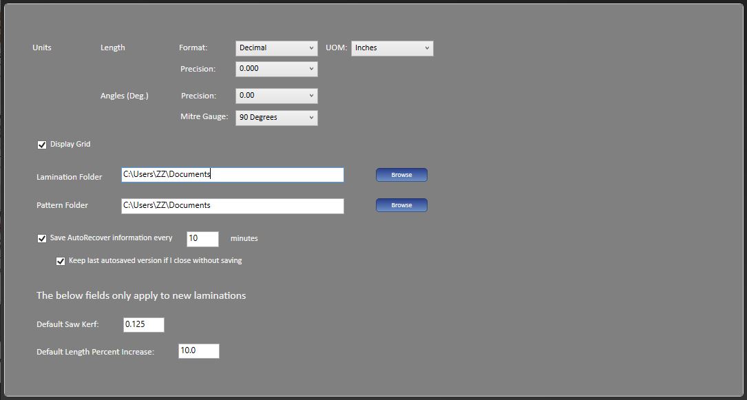
Run the program and select the ‘App Defaults’ Button and define the parameters that will apply to the application as a whole. Changes to most of the the parameters will affect the current lamination, others will only apply when creating a new lamination.
Next select [File][New] from the main menu.
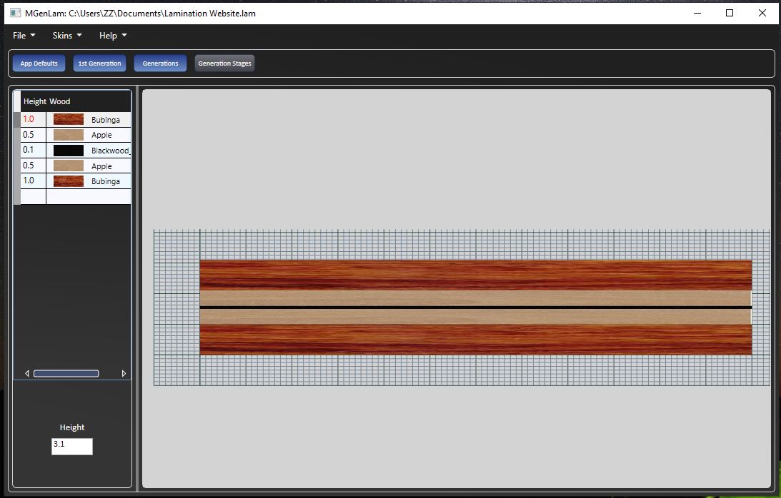
The '1st Generation' view is displayed where you add the wood layers that comprise the initial lamination. Each entry in the data grid corresponds to a layer in the lamination with a specified width and wood species.
Once the 1st generation lamination is specified you can start defining the operations to be applied in the Generations view. Select the 'Generations' button to display the Generations view. On the right panel in the view the generation number is set to 2, the number of segments is set to 12 and the lamination type is set to Segments. The saw kerf is set to the value specified in the App Defaults view. The data grid contains one row for the data describing the operations to be applied in the second generation. After the data in the row is specified press the enter key and the effects of the operation will be displayed in the view. At this point you can go back to the 1st Generation view and modify the lamination layers or change the data for the 2nd generation or change the generation number to 3 and fill in the data for the 3rd generation. If more generations are desired you can continue to increase the generation number. You can also reduce the generation number and the previous data will be retained.
To view the intermediate steps that were used to create the lamination select the 'Generation Stages' button. This view contains a list of all the operations that were performed for each generation. Select an entry and the view displays the current state of the lamination after that operation.
File Extensions
|
File Type |
Extension |
|---|---|
|
Lamination File |
‘.lam’ |
|
Pattern |
‘.cpn’ |
Program Constraints
The program enforces the following constraints
|
Field |
Minimum |
Maximum |
|---|---|---|
|
Wood Layer Width (inches) |
1/128 (0.0078125) |
36 |
|
Generation Number |
2 |
10 |
|
Generation Angle (Deg.) Mitre Angle 90 Deg |
10.0 |
90.0 |
|
Generation Angle (Deg.) Mitre Angle 0 Deg |
0.0 |
80.0 |
|
Interval (inches) |
0 |
20 |
|
Start Percent |
0.0 |
100.0 |
Saw Kerf (inches) |
1/64 (0.015625) |
0.25 |
|
Number of Segments |
1 |
64 |
Program Structure
The program is structured with a main menu at the top followed by a row of buttons under the menu for selecting views and the remaining area displaying the individual views. The four views are the ‘App Defaults’, ‘1st Generation’, ‘Generations’, and ‘Generation Stages’.
Main Menu
- File
- Save – Save the current lamination (if the lamination has not been previously saved a dialog allow the user to provide a file name)
- Save As – Save the current lamination with a new file name
- Open – Open a dialog to select an existing saved lamination.
- New – Create a new lamination.
- Output Plan
- Print Lamination Report - Print a file that contains the information displayed for the lamination and instructions for creating the lamination in wood.
- Output All Details CSV - Print out a CSV file that contains the parameters usefull in creating the lamination pattern.
- Versions - Display any 'AutoRecover' files for the currently opened lamination. Selecting one and clicking on 'Ok' will replace the current opened lamination.
- Close – Close the current lamination and allow the user to specify if the current lamination should be saved if changes have been made since the last time it was saved.
- Exit – Close the program and if there is a current lamination allow the user to specify if the current lamination should be saved if changes have been made since the last time it was saved.
- Skins
- Blue / Dark – User interface has a dark background with blue buttoms and white text
- Silver / Dark – User interface has a dark background with Silver buttoms and white text
- Blue / Light – User interface has a light background with blue buttoms and black text
- Help
- View Help - The address of this user guide on the internet
- About MGenLam - Information about the MGenLam program
- Whats New - A list of the program changes in the different versions
Application Defaults
The AutoRecover features saves copies of lamination files at a user definable fixed interval. The files can be recovered if MGenLam closes unexpectedly, for example, during a power failure. When a lamination is open in MGenLam the current version can also be overwritten by an auto recoved version. The auto recovered copies are saved to a folder in the 'Lamination Folder' with a name based on the lamination name and a timestamp, as an example 'MyLamination(BI20221212142015357)'. The file names are based on the lamination name, 'autoSaved' and a timestamp. As an example 'MyLamination((autoSaved-20221212162539357)).lamb'. When a lamination file is closed the 'autoSaved' files are deleted.
The AutoSave feature saves a copy of the lamination file if the file is closed without saving changes. The auto save copy is saved to the same folder as specified in the AutoRecover feature. The file name is based on the lamination name, 'unsaved' and a timestamp. As an example 'MyLamination((unsaved-20221212162539357)).lamb'. If changes are saved when the lamination file is closed the auto recover folder is deleted.
The program saves the application defaults externally so any changes made will be retained when to program is closed. The following default will be immediately applied.
|
Field |
Description |
Length: Format |
Controls the display format of length fields in the application (Decimal or Fractional). Note that length values can be always be input in either format. |
|---|---|
|
Length: UOM |
The units of measure specified applies to the entire application for both input and output of length values. If the Format is Decimal the available units are inches, centimeters and millimeters. If the Format is Fractional the units are inches |
|
Length: Precision |
Controls the display precision of length fields in the application. If the Format is Decimal the available precision options are '0.0', '0.00', '0.000', and '0.0000'. If the Format is Fractional the precision options are '1/16', '1/32' and '1/64'. When values are displayed normal rounding rules are applied. |
|
Angle (Deg.): Precision |
Controls the display precision of angle fields in the application. The precision options are '0.0', '0.00', '0.000'. When values are displayed normal rounding rules are applied. |
|
Angle (Deg.): Mitre Scale |
Specifies the reading on the mitre gauge when the gauge surface is perpendicular to the saw blade. The angle entered for generation cut lines will be relative to this reading. The options are '90 Degrees' or '0 Degrees'. |
|
Display Grid |
Display a grid when displaying the lamination images. If the units of measure are inches and the length format is decimal the grid contains 10 subunits per inch, if the length format is fractional the grid contains 16 subunits per inch. If the units of measure are centimeters the grid contains 10 subunits per centimeter. If the units of measure is millimeters there are no subunits. |
|
Initial Corner |
Specifies the corner where the initial cut line starts (Lower Left, Lower Right, Upper Left, Upper Right). Note that the wood strips are numbered from the initial corner. If the initial corner is on the left the wood strips are numbered from left to right. If the initial corner is is on the right the wood strips are numbered from left to right. |
|
Save AutoRecover information every 'Interval' minutes |
The AutoRecover checkbox allow you to enable or disable the auto recover feature. The interval is the number of minutes that elapse between saves. The checkbox is initially enabled by default and the default interval is 10 minutes. |
|
Keep last autosaved version |
The AutoSave checkbox allows you to enable or disable the AutoSave feature. When AutoSave is enabled a copy of the current vessel is saved to the AutoRecover folder if the vessel is closed without saving. The checkbox is initially enabled by default. |
|
Lamination Folder |
The default folder used for lamination files and output files |
|
Pattern Folder |
The default folder used for pattern files |
The following application defaults are used when creating a new lamination. The defaults are:
|
Field |
Description |
|---|---|
|
Saw Kerf |
The thickness of the saw kerf when the cross cutting the lamination |
|
Length Percent Increase |
The percentage increase added to the calculated initial lamination length |
1st Generation
This is where you specify the wood strips that make up the 1st generation of the lamination.
Wood Strip Attributes
|
Attribute |
Description |
|---|---|
|
Number |
A read only field indicating the wood strip number. This is useful when scaling the total height. |
|
Width |
The width of the wood layer |
|
Wood |
The wood species used in the layer |
Context Menu
Clicking on the data grid surface with the right mouse button opens the context menu.
|
Item |
Description |
|---|---|
|
Insert Above |
Insert a wood layer above the currently selected layer |
|
Insert Below |
Insert a wood layer below the currently selected layer |
|
Copy Below |
Copy the currently selected wood layer and insert it below |
|
Move Row Up |
Switch the position of the currently selected wood layer with the layer immediately above |
|
Move Row Down |
Switch the position of the currently selected wood layer with the layer immediately below |
|
Copy All Below |
Copy all of the wood layers and add them below the bottom wood layer |
|
Mirror Image Below |
Copy all of the wood layers and add them below the bottom wood layer in the reverse order |
|
Scale Total Height |
Open a dialog that allows scaling the total height of the wood layers with allowing for exceptions |
|
Replace Wood |
Open a dialog that allows the replacement of a wood in any layer with another wood |
|
Delete Row |
Delete the selected row. The selected row can also be deleted with the Delete key |
Lamination Width
The calculated width of the lamination board
Generations
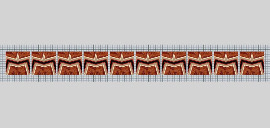
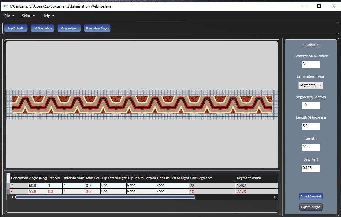
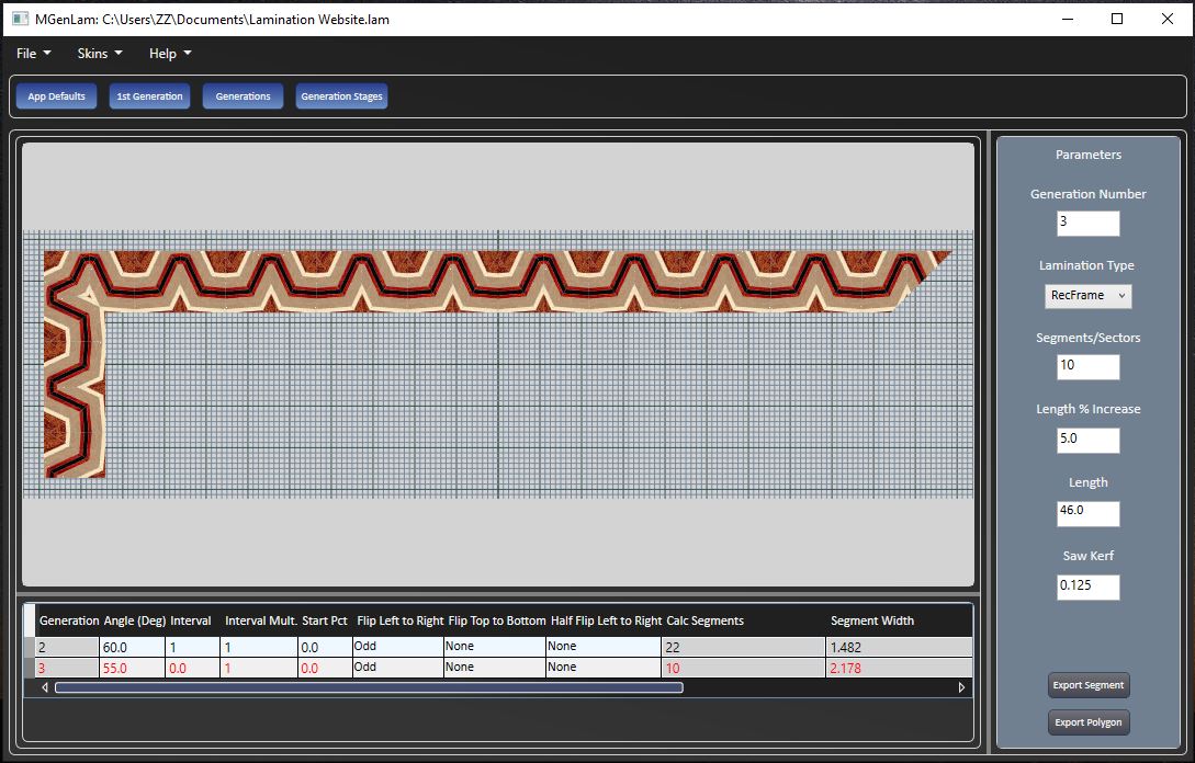
The Generations view is comprised of three parts. In the upper left is the display area showing the final results, the lower left is a data grid where the operations that are to be applied to the previous generation results are specified, and the right panel where general parameters describing the final generation to be calculated and how the result will be displayed.
Display Area
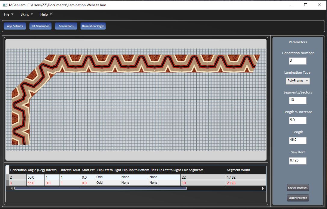
The type of display is based on the Lamination Type specified in the right panel. The following images show the type of output.
Data Grid
|
Field |
Description |
|---|---|
|
Generation |
The generation number |
|
Angle (Deg.) |
The cut angle based on the mitre scale setting in the AppDefaults view. The cut is made from the initial corner |
|
Interval |
The horizontal distance between cut lines. This field is only required for the 2nd generation. If the value of this field is zero the interval is derived from the segment length from the previous generation. Note that a segment is made up of two cut strips. A non-zero value can be specified to create a non-aligned pattern between wood strips. |
|
Start Pct |
The percentage of the cut interval where the first cut starts. Moving the position of the first cut for a given generation will change the resulting pattern. Note that changing the position for the 2nd generation will have no effect on the pattern. |
|
Flip Left to Right |
A combo box that provides three options for operations that can be performed on the cut strips. 'None' indicates that no operation is to be performed. 'Even' indicates that even numbered strips (2, 4, 6, ...) will be flipped from left to right. 'Odd' indicates that odd numbered strips (1, 3, 5, ...) will be flipped from left to right. |
|
Flip Top to Bottom |
A combo box that provides three options for operations that can be performed on the cut strips. 'None' indicates that no operation is to be performed. 'Even' indicates that even numbered strips (2, 4, 6, ...) will be flipped from top to bottom. 'Odd' indicates that odd numbered strips (1, 3, 5, ...) will be flipped from top to bottom. |
|
Flip Half Left To Right |
A combo box that provides three options for operations that can be performed on half of the cut strips. 'None' indicates that no operation is to be performed. 'Top' indicates that only the top half of the strip is flipped left to right. 'Bottom' indicates that only the Bottom half of the strip is flipped left to right. Note that the saw kerf is taken into account and reduces the height accordingly. |
|
Full Rotate Left To Right |
A check box that indicates if the final result of the generation is rotated before the next generation is cut. If the box is checked the upper left corner becomes the upper right corner. |
|
Full Rotate Top to Bottom |
A check box that indicates if the final result of the generation is rotated before the next generation is cut. If the box is checked the upper left corner becomes the lower left corner. |
|
Calc Segments |
A read only field that shows how many segments are calculated in each generation. A segment is made up of 2 cut strips. |
|
Segment length |
A read only field that shows the segment length. |
|
Segment Width |
A read only field that shows the segment width |
|
2nd Midpoint Angle |
A read only field that shows the angle to use for this generation so the mid point of the second strip in the input to this generation is the mid point of the initial cut interval. This value only applies if the width is specified as 0. |
|
3rd Midpoint Angle |
A read only field that shows the angle to use for this generation so the mid point of the third strip in the input to this generation is the mid point of the initial cut interval. This value only applies if the width is specified as 0. |
|
4th Midpoint Angle |
A read only field that shows the angle to use for this generation so the mid point of the fourth strip in the input to this generation is the mid point of the initial cut interval. This value only applies if the width is specified as 0. |
|
Error Message |
A read only message if an error occurs during a calculation of a generation |
The right panel parameters
|
Attribute |
Description |
|---|---|
|
Generation Number |
The final generation to be calculated |
|
Lamination Type |
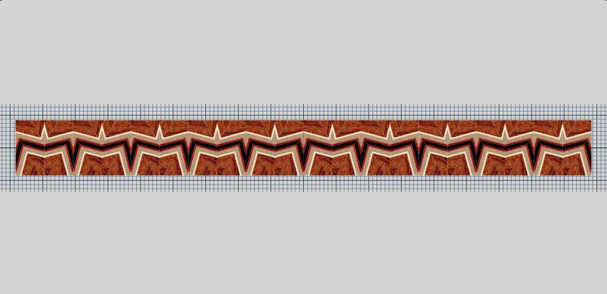
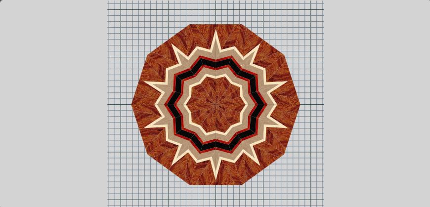
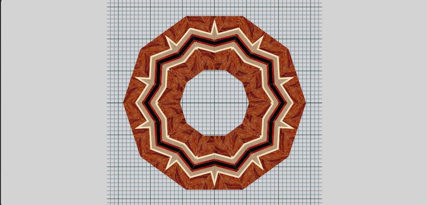
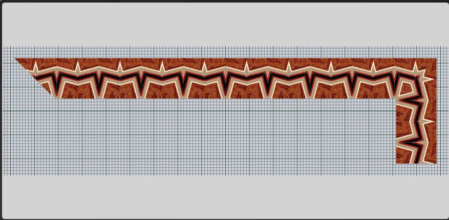
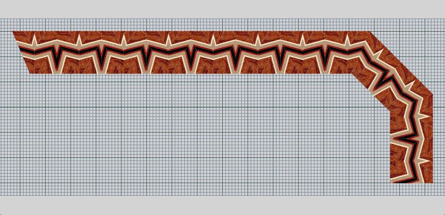
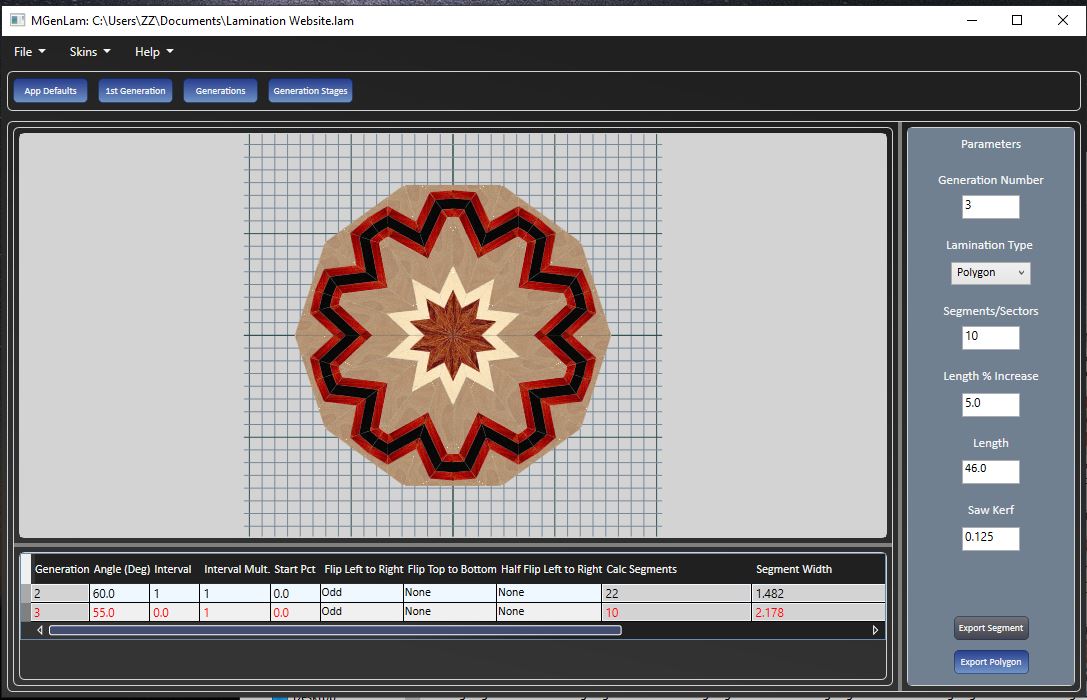
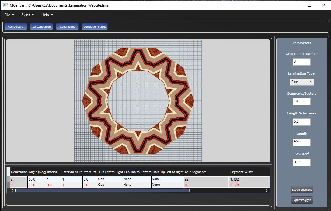
The way the lamination is displayed 'Segments', 'Rectangle', 'Polygon', 'Ring', 'RecFrame' or 'PolyFrame' . The 'Segments' display shows the required number of segments separated in a linear line. The 'Rectangle' display shows the required number of segments packed together in a linear line. The 'Polygon' display shows the required number of segments as a regular polygon adjusted so the center is loacted at the bottom midpoint of the segments. The 'Ring' display shows the required number of segments as a regular polygon adjusted so the top of each segment is on the edge. The 'RecFrame' display shows the required number of segments forming the top side of a rectangular frame with the ends cut at a 45 degree angle, a portion of the left side is included to display what the corner will look like. The 'PolyFrame' display shows the required number of segments forming the top side of a frame with the left two segments angled at 45 degrees, a portion of the left side is included to display what the corner will look like. |
|
Segments |
The required number of segments to be calculated |
|
Length % Increase |
The percent increase added to the minimum required 1st generation length |
|
Length |
the calculated 1st generation length with the length adjustment applied |
|
Saw Kerf |
the thickness of the saw kerf. |
|
Export Segment |
A button to export a segment pattern if the lamination type is 'Segments'. When importing the pattern into SegTurn the segment width corresponds with the ring height and the segment length corresponds with the wedge outside length. |
|
Export Polygon |
A button to export a polygon pattern if the lamination type is 'Polygon' |
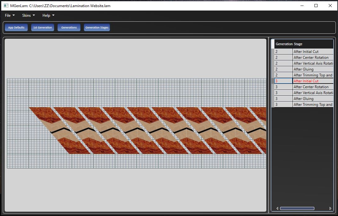
Generation Stages
The Generation Stages view provides a list of the operations that are applied for each generation. The operations are listed in the order that they are performed. When an operation is selected the display shows the state after the operation was applied.
The Operation Data Grid
|
Operation |
Description |
|---|---|
|
Generation Number |
The generation on which the operation was performed |
|
Operation |
The description of the operation |
The Available Operations
|
Operation |
Description |
|---|---|
|
After Initial Cut |
The strips remaining after the cuts. The strips are separated by the saw kerf |
|
After Center Rotation |
Rotating the cut strips to the vertical position |
|
After Flip Left To Right |
Flips the cut strips over from left to right |
|
After Flip Top to Bottom |
Flips the cut strips over from top to bottom |
|
After Gluing |
Gluing the cut strips together |
|
After Trimming Top and Bottom Edges |
Trimming the top and bottom edges to make the lamination rectangular |
|
After Flipping half Left to Right |
Flipping either the top or bottom half of the strip left to right. |
|
After Full Rotation Left to Right |
Rotating the entire glued and trimmed result left to right. |
|
After Full Rotation Top to Bottom |
Rotating the entire glued and trimmed result top to bottom. |
|
Segments After Polygon Cut |
Display of the segments after cutting to for the polygon. |
|
Segments After Ring Cut |
Display of the segments after cutting to form the ring. |
Output Plan
There are two different ways to output lamination information. The two reports compliment each other and both should be output.
Print Lamination Report
This report contains four sections. The first section contains general information. The second section describes the 1st generation data. The third section describes the remaining generations. The fourth section describes the steps required to create the multi generation lamination.
Output All Details CSV
This output consists of a report that can be input into a spreadsheet program. The report consists of three sections. The first section describes the 1st generation wood layers with three columns that are 'Number', 'Width' and 'Wood'. After the wood layer list the following fields are listed
Units - the units that lengths are displayed in.
Mitre Scale - the setting if the mitre scale.
Width - the total width of the wood layers.
Saw Kerf - the width of the saw cut.
Initial Corner - The corner if the board where the initial cut line begins.
The second section describes the remaining generations and consists of 14 columns that are 'Generation', 'Angle','Interval', 'Cut Start Offset', 'Cut End Offset', 'Flip L to R', 'Flip T to B', 'Half Flip T or B', 'Full Rotate L to R', 'Full Rotate T to B', 'Number Segments', 'Segment Length', 'Segment Width', 'Final Length'.
Generation - the generation number
Angle - the cut angle
Interval - the horizontal distance between beginning of cut lines.
Cut Start Offset - When the start percent is 0 this value will be 0. If the start percent is greater than 0 this is the horizontal distance to where the first cut line begins.
Cut End Offset - this is the distance from the board end where the first cut line ends.
Flip L to R - flip the wood strip over from left to right.
Flip T to B - flip the wood strip over from top to bottom.
Half Flip T or B - Cut the strip in half and flip the top or bottom over from left to right.
Full Rotate L to R - flip the entire board over from left to right.
Full Rotate T to B - flip the entire board over from to to bottom.
Number of Segments - the number of segments created in this generations.
Segment Length - the length of a single segment within the board.
Segment Width - the width of a segment, this is also the board width.
Final Length - The final length of the board
The third section contains a list of the start positions of the cut lines measured from the initial corner.
The print lamination report describes how to use this information.
Construction Tips
- Before making any cuts the saw blade must be perpendicular to the surface. It is preferred to make a test cut in a board and check the angle with a machinist square. Hold the wood and square up to a light and make sure there is no light showing through.
- When sanding the surfaces of glued up boards the lamination lines on the ends of the board must remain perpendicular to the surface.
- When cutting strips the saw blade must be perpendicular to the cutting surface. This is important for cross cut strips to align when they are flipped over and joined to the previous strip.
- For a given angle and cut interval the cross cutting of strips must be repeatable to a high degree of accuracy